Convair YF2Y-1 Sea Dart

Why not share your information on your latest creation
Alex Jones
Posts: 156
Joined: January 20th, 2016, 11:37 pm
Contact:

Re: Convair YF2Y-1 Sea Dart

Postby Alex Jones » September 8th, 2020, 10:16 am

I like the systems side of things and always enjoy this part of any installation but before I start on the electronics I had to accept that no matter how hard I try water will find it’s way in. This maybe from wet hands while servicing, seals below the waterline or spray getting inside the hatch seals, either way it’s worth protecting the electronics. If I accept that it could get wet inside then all the electronics have to be splash proof so I designed splash proof boxes to protect the electronics. These are 3D printed SLS items with an O-ring seal and perspex lid. Below are some images from the CAD work I did…

Image43696B13-B225-4C32-9D19-752CB334EB62 by Alex Jones, on Flickr

ImageA3DECA13-799D-40AF-A224-F8C3F2E24892 by Alex Jones, on Flickr

I have provided cooling for the CB400 and pneumatic boxes which will maintain these areas at ambient. Tests with the equipment in the centre fuselage show an increase above ambient of 10 degrees which is well within the operating range of the electronics so I decided not to include cooling in these areas. We’re well within a decent safety margin if operating the aircraft in temperatures that don’t exceed 40°C/104°F

Steve Perry
Posts: 227
Joined: July 12th, 2015, 7:47 pm
Contact:

Re: Convair YF2Y-1 Sea Dart

Postby Steve Perry » September 8th, 2020, 11:10 pm

Will you be installing any form of bilge pump ?
Another thought is will you be adding any "buoyancy", typically large pieces of expanded polystyrene sufficient to stop it sinking should the worst happen ?

Alex Jones
Posts: 156
Joined: January 20th, 2016, 11:37 pm
Contact:

Re: Convair YF2Y-1 Sea Dart

Postby Alex Jones » September 9th, 2020, 8:42 am

Hi Steve,

The bilge pump is a good idea and I suspect I'll end up fitting one. I've been experimenting with various pumps for one of our other projects and have found car screen washer pumps work well.

I started the main installation by removing everything from the engine test stand and installing this into place inside the fuselage. I used new Festo 6mm tubing but other than that everything is exactly as it was on the stand. All the associated turbine wiring was run through the fuselage. In the CAD images above you can see the carbon tubes that tie the formers together, these are 18mm tubes and also act as conduits for the wiring. Before going to the effort of making everything neat the turbine electronics were all tested to ensure everything worked as expected. I have two Digitech CTU’s on each turbine which have already proved to be very useful.

ImageB3BC8409-6A38-4F3D-A42F-570DAE3D7E46 by Alex Jones, on Flickr

Image9061F850-5FAD-4671-8D7F-772C2B459E99 by Alex Jones, on Flickr

It’s then just a matter of running all the other wires, this took some time….

ImageA555436D-8AAD-4DFC-AEE3-1EAC549C0FAE by Alex Jones, on Flickr

ImageADD8A596-0E29-4163-A133-B0F532AB3ED8 by Alex Jones, on Flickr

Alex Jones
Posts: 156
Joined: January 20th, 2016, 11:37 pm
Contact:

Re: Convair YF2Y-1 Sea Dart

Postby Alex Jones » September 10th, 2020, 7:53 am

With all the electrics in the aft section tested and working as planned I can make things a little neater. In the electronics box just forward of the hoist point we have a Jeti REX7A receiver, after burner light ring control, hull lights control and battery to power these lights. Ignore how the antennas are placed as these will eventually be correctly polarised and poke outside the box. Further aft (not pictured) we have a Jet RSAT 900 with the antennas placed on either side of the hull.

Image91C0B3AA-4986-4BE7-B77D-ADA24B32DF02 by Alex Jones, on Flickr

Image6ACA108B-2088-4003-9F9C-C49169185A1B by Alex Jones, on Flickr

ImageD907F9C4-F347-4191-A458-F66A343BAFAC by Alex Jones, on Flickr

The turbine electronics have their own individual boxes with the ECU and CTU inside. The Deans connection is just temporary and I will be replacing these with IC5 connectors which are more suitable for anything with the possibility of getting wet. They have proved to be excellent on my Son’s RC cars.

Image2819349B-6FA4-4F5F-A149-BFE0ED65AF8E by Alex Jones, on Flickr

One last test of all the electronics and peumatics before I split the fuselage to work on the electrical connection splits. There are twenty cables running through to the front which need to be easy to connect, secure and splash proof.

Image641E02A3-CC9B-41CA-BA9A-E69564499586 by Alex Jones, on Flickr

Image0FE5D92F-7699-4B47-8532-1F292D5AFBE5 by Alex Jones, on Flickr

Dave Kellett
Posts: 119
Joined: March 4th, 2016, 7:57 pm
Contact:

Re: Convair YF2Y-1 Sea Dart

Postby Dave Kellett » September 11th, 2020, 6:45 am

Hi Alex
Can you tell me please what are the 2 cylinders that are in picture 3rd from bottom. One on top of the other approx 10 cms in diameter.
Best regards
Dave

Alex Jones
Posts: 156
Joined: January 20th, 2016, 11:37 pm
Contact:

Re: Convair YF2Y-1 Sea Dart

Postby Alex Jones » September 11th, 2020, 10:07 am

Hi Dave,

These are the fuel air traps, one for each fuel system.

With the fuselage split I can get on with what seems to be a never ending list of jobs for the back end. Starting with the auxiliary air intakes. These are prototypical in that they do feed into the main intake. They remain open until the aircraft is >15kts and >60% thrust, when these conditions are met they close. These aren’t required from an operational point of view so are purely a scale feature although a little extra intake area won’t hurt. We expect this model to be relatively slow in the water at high power settings until the skis un-port and then get up onto the plane. We will play around with the close settings so it looks nice and scale during the takeoff run.

The intakes are constructed from various 3d printed components using SLA and SLS printing along with carbon hinges and actuators connected to some small MKS servos mounted at the top of the housing.

ImageB675BF8F-778E-4939-AFB2-5C315DF60963 by Alex Jones, on Flickr

ImageA733FEF0-AE19-4C19-920A-04183F94B9BD by Alex Jones, on Flickr

Image8B375AE3-7211-4FED-9D41-21E2A8B4B14A by Alex Jones, on Flickr

Image9062EFA7-DB4D-452B-9049-AC26815A3C4A by Alex Jones, on Flickr

A video showing their operation during a dry fit before we had the model painted.

https://youtu.be/AhWylmR1rjI

Alex Jones
Posts: 156
Joined: January 20th, 2016, 11:37 pm
Contact:

Re: Convair YF2Y-1 Sea Dart

Postby Alex Jones » September 14th, 2020, 9:17 am

The intakes have been causing me a headache as they are very difficult to remove. They also require the turbines to be removed which very quickly got on my nerves. During the build these need to be installed and removed frequently which wasn’t time efficient and more importantly I need to push forward the intake just in-front of the turbine to get the vertical stabiliser bolt in place. With all this in mind I decided to split the intake again over the tank hatch. This allows me to easily remove the intakes and easily maintain the fuel tanks and ski actuators without spending hours removing all the intake system.

I made some 3D printed intake rings with a seal grove and split the forward intake as shown.

Image6D78E78A-2B6F-49F2-9124-C968B37B8A2D by Alex Jones, on Flickr

Image2DC45718-1A0B-41B7-8BC5-0907A2BA49E3 by Alex Jones, on Flickr

Now its just a matter of removing these bolts on this section and I can access everything I need quickly. While at the lake I only have to do one side to facilitate the installation of the vertical stabiliser which speeds things up dramatically.

Image819DBF90-C5C2-40F4-A665-3C8B11A2297F by Alex Jones, on Flickr

Alex Jones
Posts: 156
Joined: January 20th, 2016, 11:37 pm
Contact:

Re: Convair YF2Y-1 Sea Dart

Postby Alex Jones » September 16th, 2020, 9:23 am

The tail wheel on the SeaDart was a castor so it could be easily manoeuvred by ground crew while on its beaching gear. I decided to make a fixed version as this could be easily integrated into the structure. The beaching gear wheels are located forward of the CG so it does have to takes its fair share of the load.

Image0335B8CC-67D5-4FDE-AA4B-32F356307A23 by Alex Jones, on Flickr

3mm carbon was used to tie the wheel into the keel beam.

ImageEB7B785B-BD30-441B-8B85-BFB81546F791 by Alex Jones, on Flickr

ImageIMG_4113 by Alex Jones, on Flickr

Slotted over this carbon structure is a carbon composite pre-preg fairing bonded in place.

Image485AAE50-FCEA-4098-8999-0762A6E2F8D7 by Alex Jones, on Flickr

The wheel is Aluminium with a 3D printed tyre running on a Stainless Steel shaft on Phosphor Bronze bushings. On top of this we made 3D printed fairing that simulates the look of the castor fairing.

ImageE6AE5AB4-37DF-4EC8-9D12-FFD7777A80BB by Alex Jones, on Flickr

With a working tailwheel we can have the aircraft on the scale beaching gear and in theory it can move down a slip way into the water under its own power. Like the real one there will need to be a rope attached to the beaching gear so it can enter the water at a sensible speed.

Dave Kellett
Posts: 119
Joined: March 4th, 2016, 7:57 pm
Contact:

Re: Convair YF2Y-1 Sea Dart

Postby Dave Kellett » September 17th, 2020, 7:14 am

Hi Alex,
Yet again some fabulous detailed photographs and text about this amazing project, what concerns me tho is that, you mention that it will be in theory be able to enter the water under it's own power, if that is the case then, that means we are all going to be denied seeing Phil Clark with his shoes / socks off, and trousers rolled up and holding the pointy end into the water. :cry: :lol: :lol:
Once again thanks for this latest information

Dave

PS
Stay safe and keep smiling Phil.

Alex Jones
Posts: 156
Joined: January 20th, 2016, 11:37 pm
Contact:

Re: Convair YF2Y-1 Sea Dart

Postby Alex Jones » September 17th, 2020, 10:12 am

Don't worry Dave we can always give him a push if it comes to it! :)

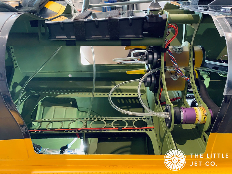
While things are easy to access I tested the fuel systems on both tanks. It’s a good opportunity to check for any small leaks, it beds the pumps down especially as they can run at full thrust voltage and lastly I can fine tune the pump factors so the fuel state telemetry is accurate. It is not always necessary on models to do this as access is easy and it’s not a big job to change things although this isn’t the case in this instance. Usually leaks appear at higher voltages and if you’ve purchased a used turbine pay close attention to the barbs on the pumps as people like to cut tubing off with a scalpel. This often leaves very small indents on the barb ridges and it will leak on thrust setting above idle.

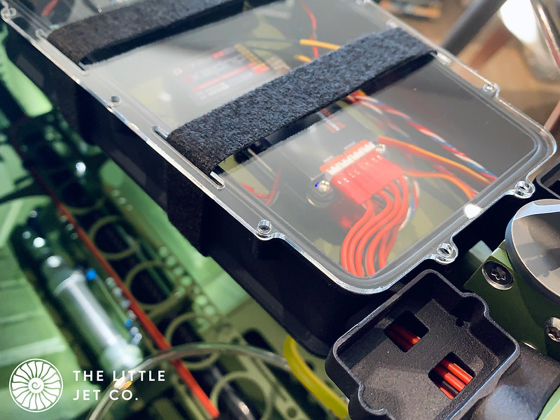
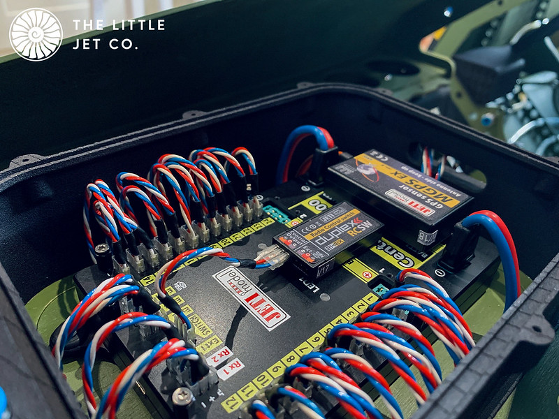
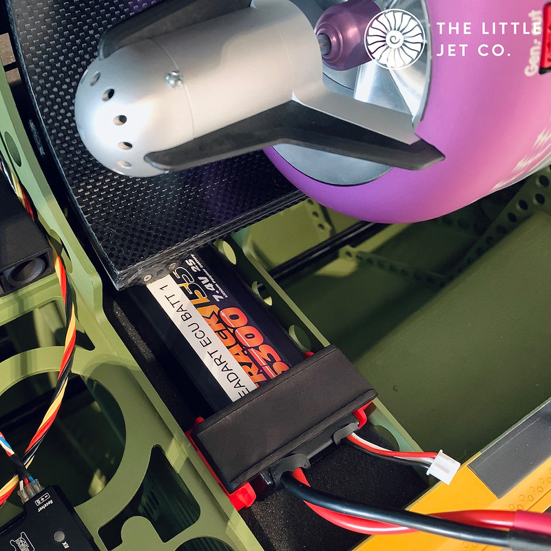
Following the theme of splash proofing anything electrical I have used high capacity RC car batteries in this case Overlander 7.4v 2S 5300 Lipos. These have worked well on our ARRMA cars which get drenched so should cope with this type of use well.
They are held in with a 3D printed latch, you just squeeze the red parts into the battery and it releases.

Image1FC90CFF-E03A-48DB-8622-B9A2FBC9406E by Alex Jones, on Flickr

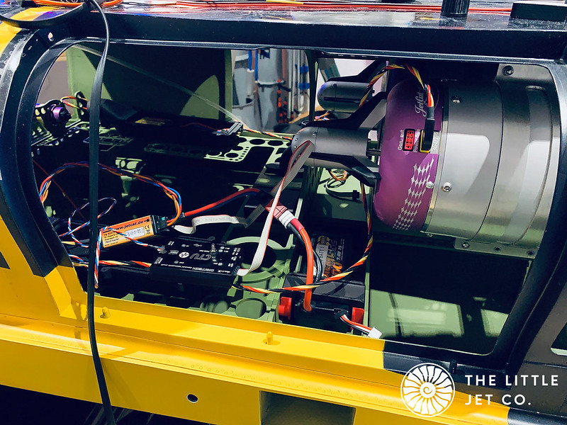
I’ve mentioned before we are using CTU’s from Digitech and the twin turbine dashboards works well. To make use of the fuel telemetry the pump factor needs to be calibrated. After running fuel through each pump I then adjust the pump factor so the fuel remaining reads zero as the main tank starts to empty.

A short video shows the result… The pump factor settings are found in the CTU menu.

https://youtu.be/R0JRNt77mlU

Image
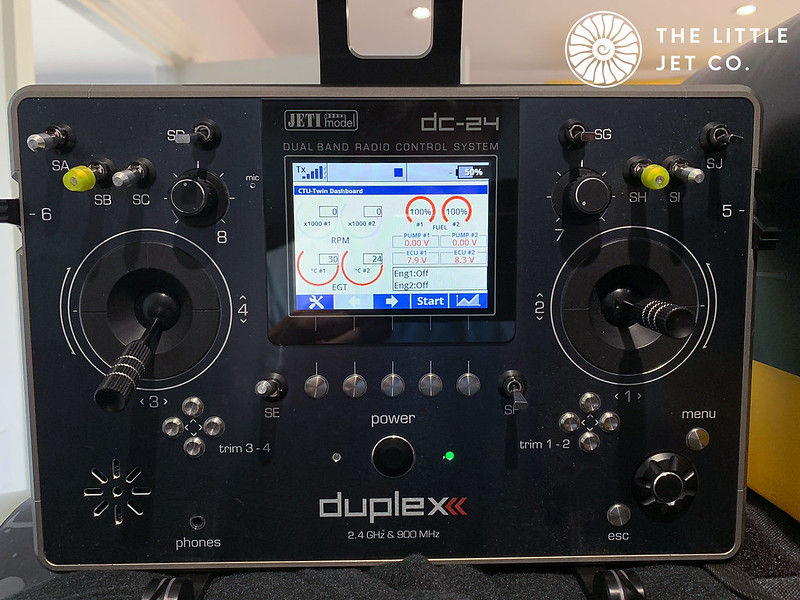
3328429A-6733-4BF5-8F7D-1BAEA8D103B4 by Alex Jones, on Flickr

I normally only fill the fuel systems on my jets at a rate equivalent to full thrust, It can no doubt cope with more but this way I’m sure I won’t over pressure the tank.

Image1A0D14DD-C199-4FDE-9E68-637F9F545D88 by Alex Jones, on Flickr

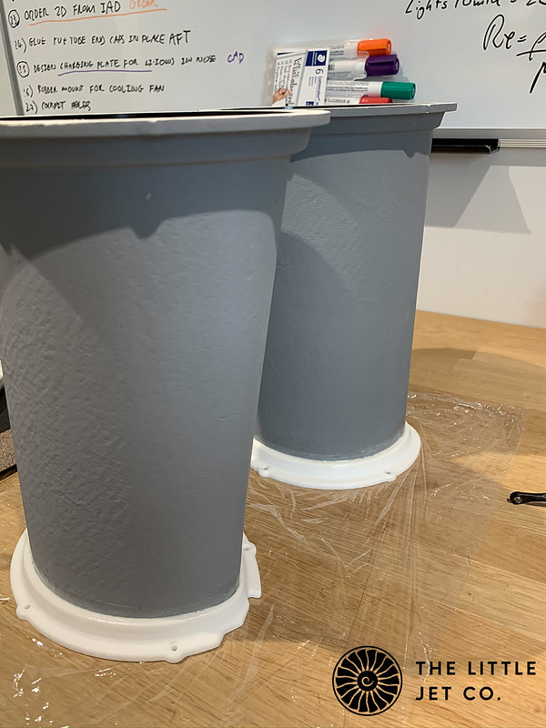
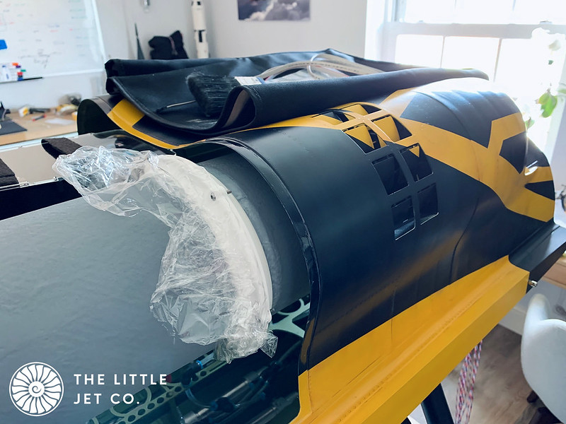
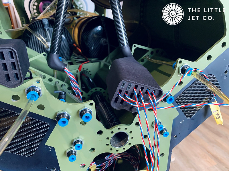
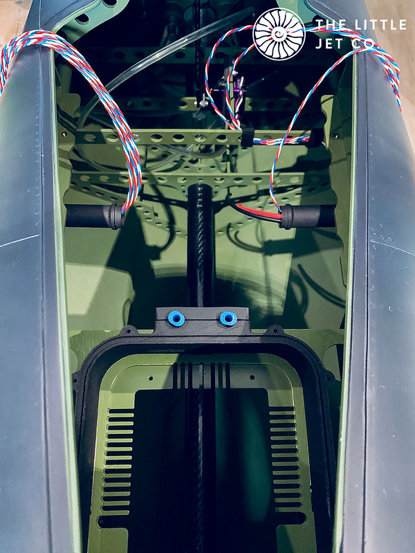
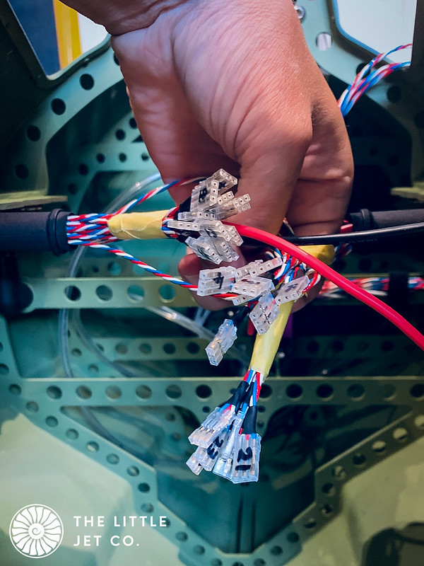
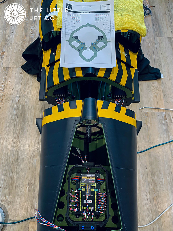
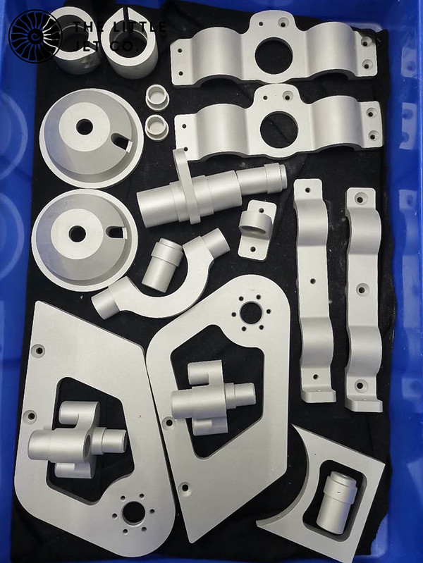
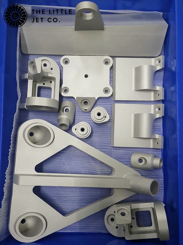
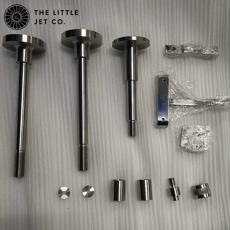
While Ive been working on this I have come up with a plan and designed some components that will allow us to easily assemble the fuselage halves and join the electrics easily and seal them from any water. The start of the process below.

Image34362D71-D36E-4949-A7F0-F639D9D142BD by Alex Jones, on Flickr

Cary Bailey
Posts: 323
Joined: January 26th, 2011, 7:43 am
Location: Stoke On Trent
Contact:

Re: Convair YF2Y-1 Sea Dart

Postby Cary Bailey » September 17th, 2020, 1:36 pm

Alex, a magnificent project, technically brilliant and a far distance away from the TopFlite P-51 that you started to build not so many years ago!
Thanks to you I now cherish that P-51 along with the full size aircraft that I modelled it on and have flown both on many occasions!
I wish you every success and look forward to a world class maiden flight.
All the very best
Attachments
IMG_3063.JPG
IMG_3063.JPG (329.81 KiB) Viewed 11045 times

Alex Jones
Posts: 156
Joined: January 20th, 2016, 11:37 pm
Contact:

Re: Convair YF2Y-1 Sea Dart

Postby Alex Jones » September 18th, 2020, 8:57 am

Hi Cary,

Thanks :) Good to hear from you and I'm so pleased the P51 is still going strong. I still love to build with wood and after this is finished I plan to treat myself to a traditional kit and build a large scale Tiger Moth for those lazy summer evenings!

Cheers, Alex

Alex Jones
Posts: 156
Joined: January 20th, 2016, 11:37 pm
Contact:

Re: Convair YF2Y-1 Sea Dart

Postby Alex Jones » September 18th, 2020, 8:58 am

Like the 3D printed splash proof boxes for the electronics I decided to go a similar route with the fuselage electrical split. I designed two 3D printed housings either side where I am able to push the female PowerBox servo connector into the housing for an engineered fit. These housings are SLS printed nylon which are then tumbled and died black.

ImageE04AE66B-364D-419A-87CC-6C2AA50F1195 by Alex Jones, on Flickr

Image67093BBD-6209-430F-ACA5-53D3CAB2B470 by Alex Jones, on Flickr

The rear section layout finished and tested.

Image554EB5BF-4ABB-43AA-B4B5-095389AC4DF3 by Alex Jones, on Flickr

This moves us onto the forward section which has 3D printed housings that slide and seal into the aft section housing thereby protecting the connections. To allow room to connect the wires I have around 200mm of excess cable which slides back into the long forward housing as the two halves are joined.

ImageDF325C6A-E51C-45D8-828A-CE609648C2E5 by Alex Jones, on Flickr

ImageSeaDart Fuselage Join Checklist by Alex Jones, on Flickr

Cary Bailey
Posts: 323
Joined: January 26th, 2011, 7:43 am
Location: Stoke On Trent
Contact:

Re: Convair YF2Y-1 Sea Dart

Postby Cary Bailey » September 18th, 2020, 3:06 pm

Alex Jones wrote:Hi Cary,

Thanks :) Good to hear from you and I'm so pleased the P51 is still going strong. I still love to build with wood and after this is finished I plan to treat myself to a traditional kit and build a large scale Tiger Moth for those lazy summer evenings!

Cheers, Alex

Hi Alex, the TopFlite P-51 is now in the USA at Tallulah MS alongside the full size P-51! I keep her there now to fly when I go over to fly in a warbird airshow. I also get to fly in the full size P-51. I have a few hours on the full size now but dual control only as I'm not there long enough to get fully trained, however I do fly "front seat" occasionally, so the thrill of handling the main controls whilst my friend and instructor sits in the back!!
Cary

Alex Jones
Posts: 156
Joined: January 20th, 2016, 11:37 pm
Contact:

Re: Convair YF2Y-1 Sea Dart

Postby Alex Jones » September 22nd, 2020, 8:59 am

Hi Cary,

I do love the Mustang and it’s cool your able to fly one. :) If you could email me some pictures of the model that would be appreciated as I only have some of it in Primer before I sold her. Hope you get out to the US again when able…


The electrics in the forward section are run through 3D printed conduits that feed into the main box where the CB400 is mounted. There is another box on the bottom about 25mm deep that allows any excess wire to sit in, the bottom is capped with 2mm acrylic.

ImageDEC08FE5-91E0-450D-A7A8-0677F3D89FCE by Alex Jones, on Flickr

I ran all the appropriate cables to the fuselage split ready to test each one individually, as mentioned earlier these are plugged in and the excess wire moves into the housing as the fuselage halves come together.

Image396F7E26-E34F-4D4D-ABCD-3B2F1F428EE7 by Alex Jones, on Flickr

Image2B8C02AD-1200-42F9-86E4-D9DF013A8B48 by Alex Jones, on Flickr

Image9FA06F20-7172-4907-9D6F-979384D1B7EB by Alex Jones, on Flickr

Everything was connected up and tested for the first time with all 24 channels needed. We have a second transmitter that controls the pilots head, canopy actuation and locking so it has 30 channels in total.

Image0D08A676-31F7-47D3-A75F-DB21F2780E18 by Alex Jones, on Flickr

Cary Bailey
Posts: 323
Joined: January 26th, 2011, 7:43 am
Location: Stoke On Trent
Contact:

Re: Convair YF2Y-1 Sea Dart

Postby Cary Bailey » September 22nd, 2020, 12:33 pm

[quote="Alex Jones"]Hi Cary,

I do love the Mustang and it’s cool your able to fly one. :) If you could email me some pictures of the model that would be appreciated as I only have some of it in Primer before I sold her. Hope you get out to the US again when able…


Alex, pics sent to your e-mail address.
Kind regards
Cary

Alex Jones
Posts: 156
Joined: January 20th, 2016, 11:37 pm
Contact:

Re: Convair YF2Y-1 Sea Dart

Postby Alex Jones » September 23rd, 2020, 8:33 am

Thanks Cary :)

I’ve been putting off doing the Pitot for ages as it was one of those jobs that had the potential to cause some damage if I got it wrong. I started by making a hole in the top of the vertical stabiliser which had to be exactly in line and 35mm deep to allow the pitot to have a snug push fit into the stabiliser. This took me a long time!

Image3393456A-1EB5-4171-815B-3721EC6A6989 by Alex Jones, on Flickr

Once complete I used aluminium tube which will form the base structure of the probe. With the whole made (Phew!) and a straight cut along the stabiliser to mount the probe I traced the outline scanned this into CAD and started making the fairing. This was printed using SLA allowing me to get a nice finish on the component. A Jeti Pitot is mounted in the end and everything bonded together, painted and I now have a push fit working scale Pitot.

ImageAD0E2319-8253-4248-A8D6-0915C00AA3AF by Alex Jones, on Flickr

Image1B92F074-F60D-428A-B2D1-B392BD4FD66A by Alex Jones, on Flickr

ImageD037DE2A-63A5-487A-9862-4C922407D91C by Alex Jones, on Flickr

Image32A1981B-F9AA-47BD-9884-BBA425240B90 by Alex Jones, on Flickr

Just the end to paint silver to complete the scale look and being removable it stands less chance of being broken off.

Alex Jones
Posts: 156
Joined: January 20th, 2016, 11:37 pm
Contact:

Re: Convair YF2Y-1 Sea Dart

Postby Alex Jones » September 24th, 2020, 2:03 pm

Moving onto the beaching gear… This will be really important for us and was designed in partnership with PES Performance Ltd. This can work as a stand allowing us to test the oleo extensions/retraction retract the skis and run the engines while safely sat on the beaching gear. Then can be wheeled down a slipway into the water. It has hydraulic brakes when in the full 5 wheel version or get broken down to the scale beaching gear of the full-size had. The two versions can be seen in these computer renders.

Image3EA6C98F-9757-4837-B422-37123F210F15 by Alex Jones, on Flickr

ImageD50EDF52-F976-4313-B26B-7289BE930F83 by Alex Jones, on Flickr

Alex Jones
Posts: 156
Joined: January 20th, 2016, 11:37 pm
Contact:

Re: Convair YF2Y-1 Sea Dart

Postby Alex Jones » September 24th, 2020, 2:03 pm

With the designs and drawings complete it’s just a matter of machining the components. These are all ready for hard anodising… (bar the SS stuff)

ImageDB4815A4-2602-4C4F-B6A2-3515633CB5DE by Alex Jones, on Flickr

Image98C28C2D-F8EC-4AE0-87BE-1DB8E59B59B8 by Alex Jones, on Flickr

Image13CEA21B-693F-449D-99DC-2712561B7EE8 by Alex Jones, on Flickr

Image3AAE4813-9499-4352-880C-9CC2E86585A8 by Alex Jones, on Flickr

Image1EA88432-E2F3-4C68-ACD3-CF6DFE1FA4DB by Alex Jones, on Flickr


Return to “Your New Projects”

Who is online

Users browsing this forum: No registered users and 13 guests