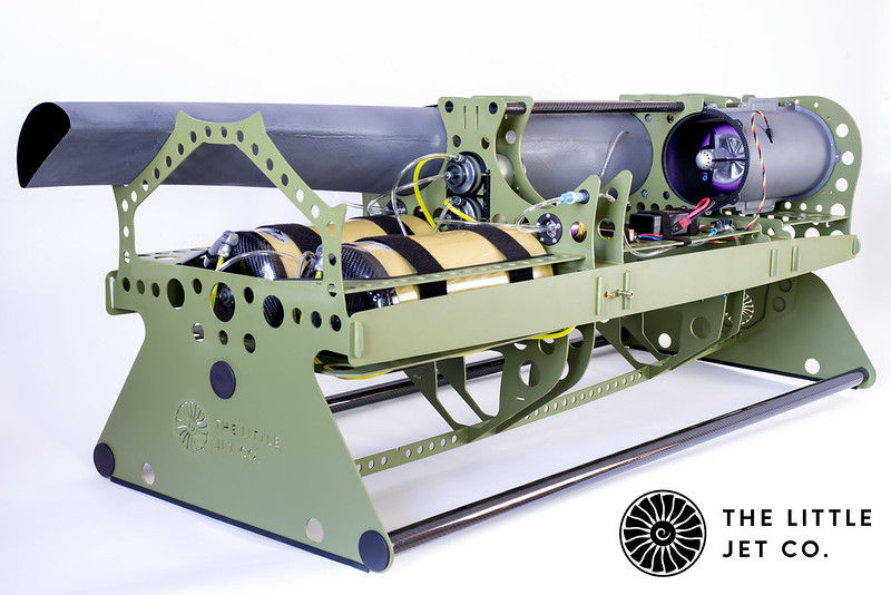
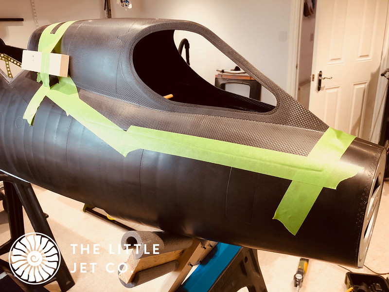
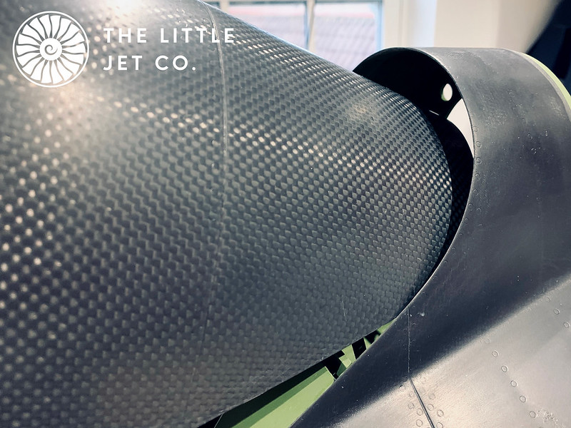
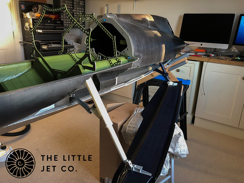
With the forward fuselage structurally complete I can move onto the rear. The purpose is to install only what is required initially to allow the ski retraction to actuate. We still don’t know how successful the ski retraction will be and with this part of the project taking a high proportion of the entire design and manufacture time I’m nervous that it won’t work…. Very nervous…
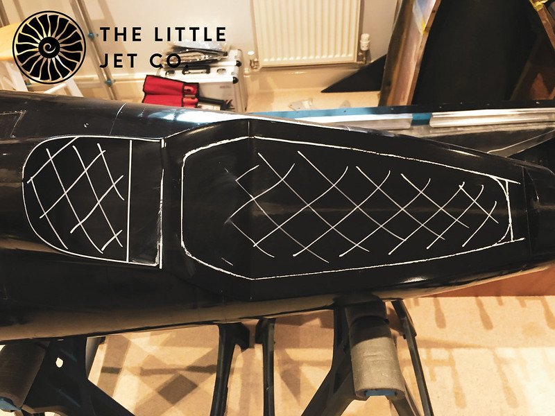
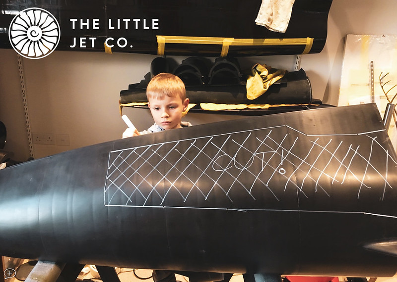
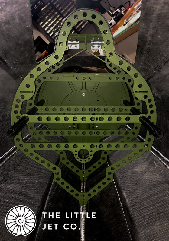
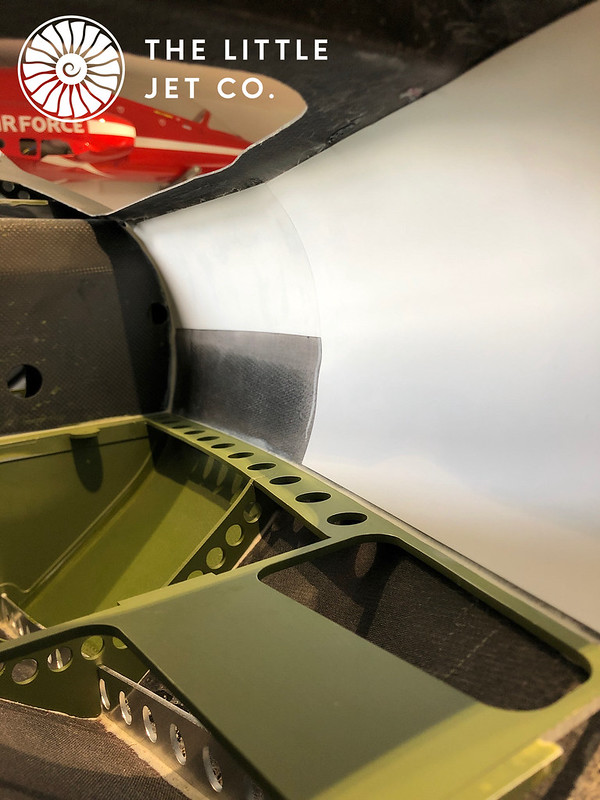
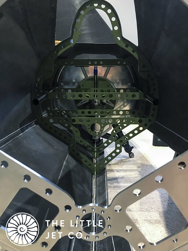
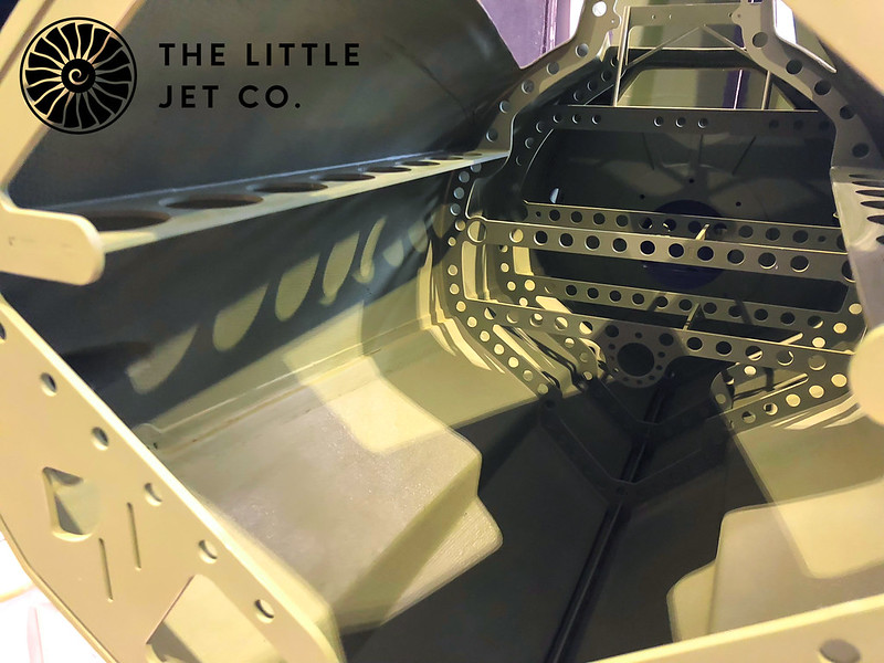
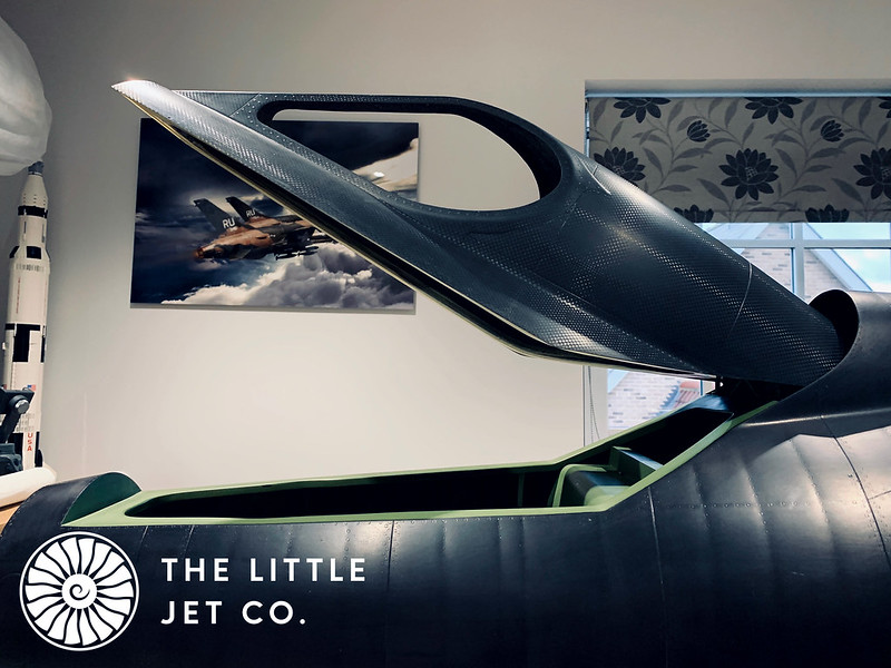
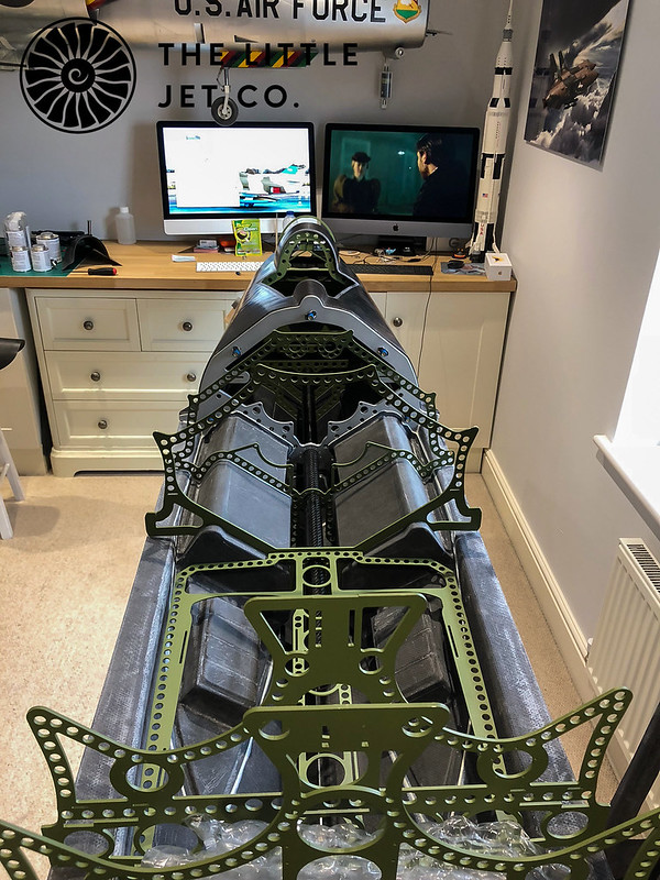
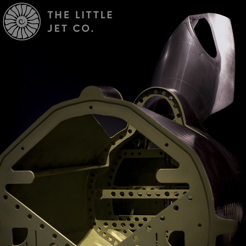
The first task was to dry fit all the formers and do the inevitable fettling to get them all to fit snugly in place. I’m primarily concerned with the first two formers in the aft section. These were fitted with the carbon ski wells in place. In conjunction with the keel beam slots, moulded return of the ski wells and formers including the main pivot block it all essentially self jigs into place. I bonded the first former and ski wells into place but left the main pivot block and second former which takes the load from the skis as I’m unsure if this part will require a re-design if the skis don’t retract.
 IMG_0141
 by
Alex Jones, on Flickr
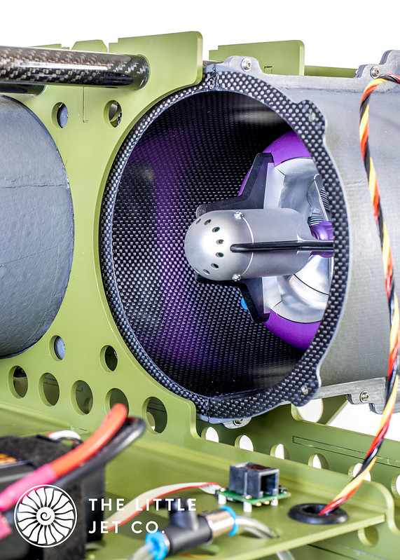
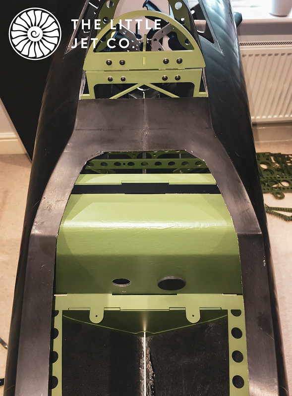
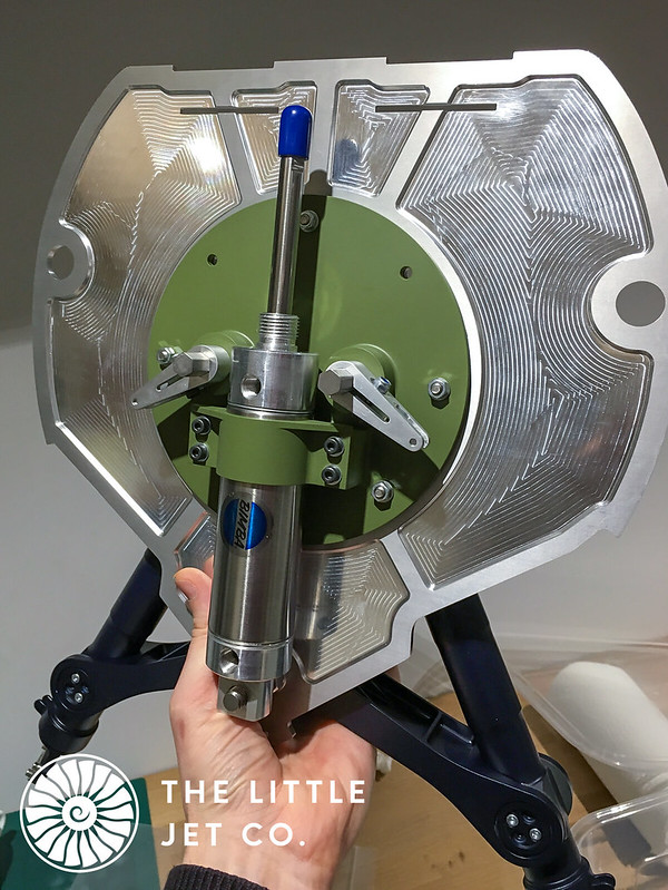
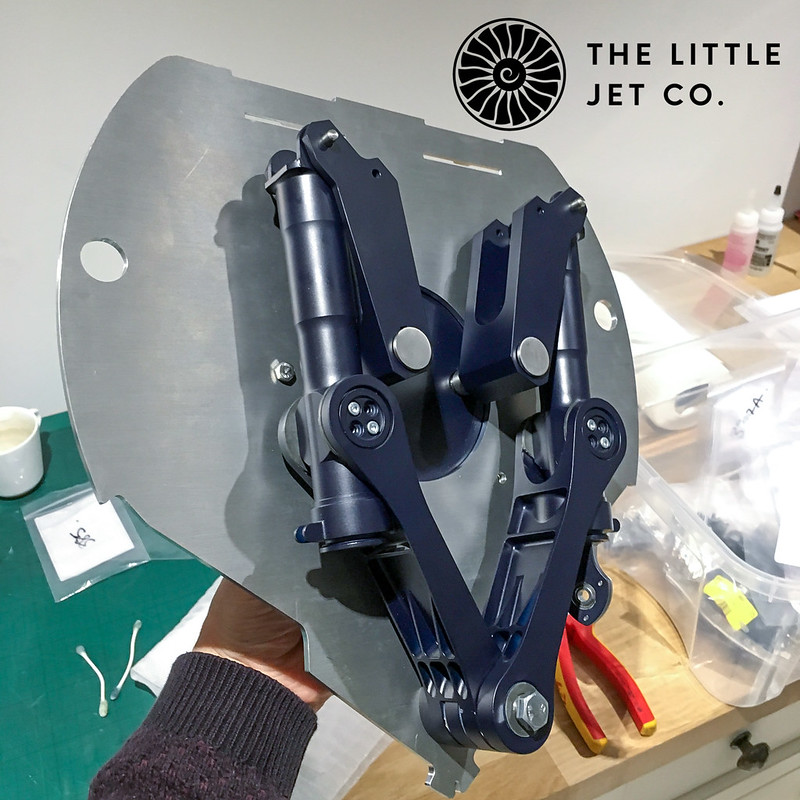
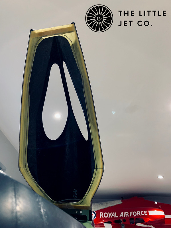
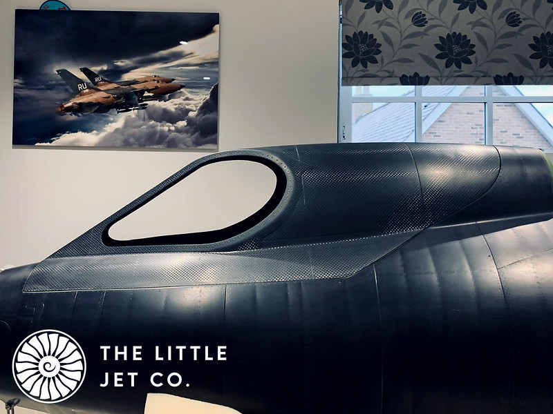
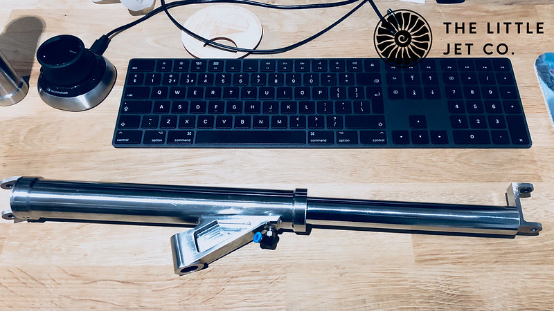
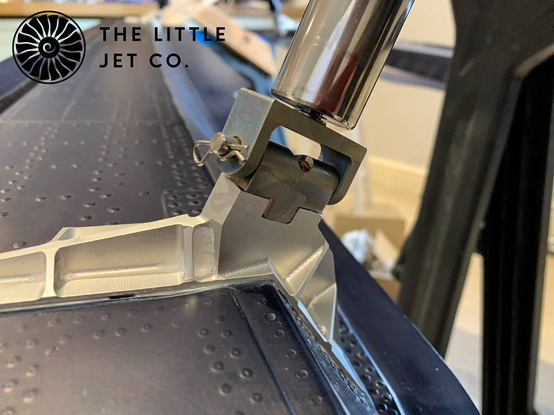
I’m now at a stage where I can fit the prototype parts of the ski mechanisms and see if the skis will push up into place by hand. It’s a different matter to actuate it prototypically but at least I can see if the mechanism folds away as designed and the ski seats correctly on the side of the fuselage.
 IMG_0213
 by
Alex Jones, on Flickr
Did I mention earlyier I was nervous? This is where all my years of being around aircraft, models, engineering, all my academic and practical experience in aerospace for the last 30 years was bundled together and drop kicked out of my brain…

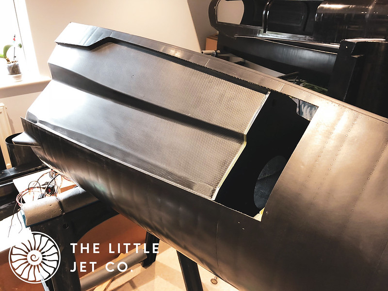
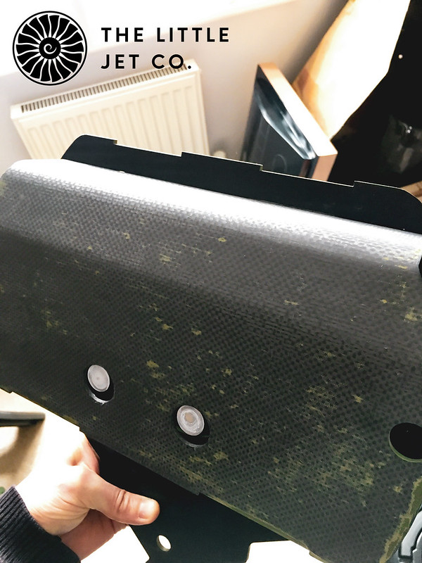
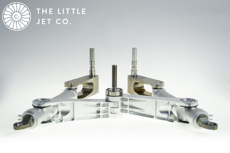
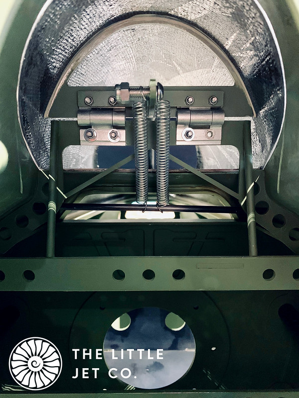
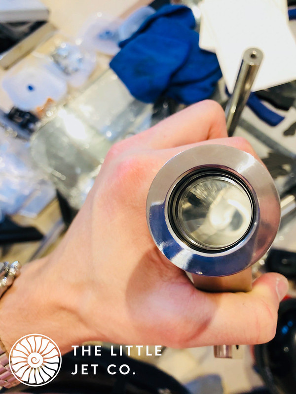
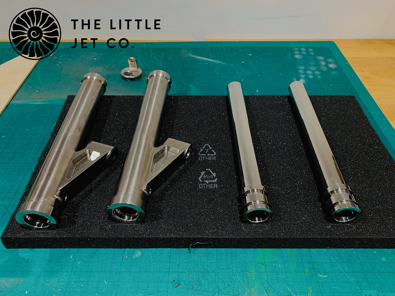
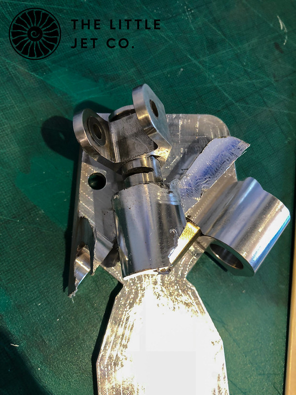
In my excitement on receiving the machined aluminium pivot block and stainless steel pivot pins I immediately installed them without any lubrication, without even checking the machined parts or removing any burrs and not installing the PTFE bushings (these were the raw machined parts with no finish post applied) After about three turns the whole thing seized inside the pivot block. The next three days were spent trying to remove the pivot block without damaging the composite fuselage or stainless steel pivot pin. After much head banging and profanity the only option left to me was to cut the block out with an angle grinder sacrificing the machined parts in order to save the fuselage. I had to remove a 2 inch square section from the carbon ski well to allow the external part of the pivot arm to fit through the ski well. I then set about destroying the pivot block taking care not to damage any of the hull composite.
It would have been unfair and just not right on my client to have charged for any of this time or replacement parts so I was rather grumpy with myself to say the least at having lost an entire week due to not engaging my brain! I did, however, manage to remove the block without compromising the composite hull.
 IMG_0216
 by
Alex Jones, on Flickr
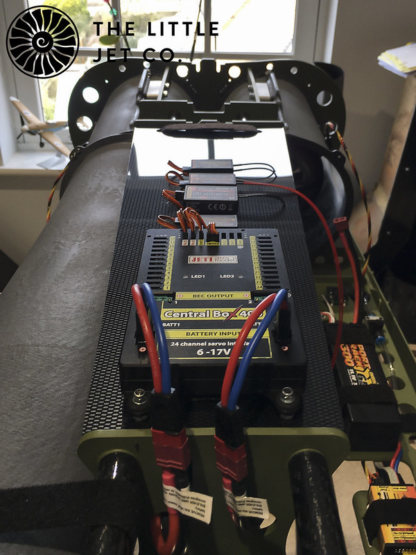
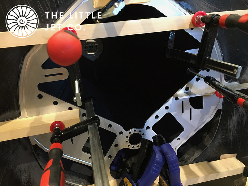
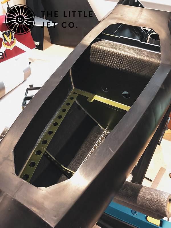
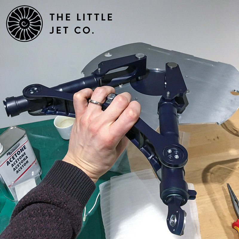
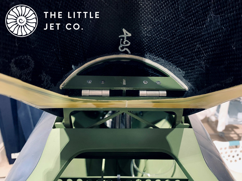
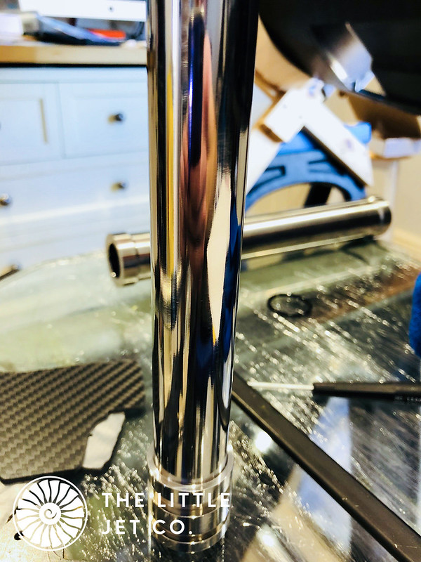
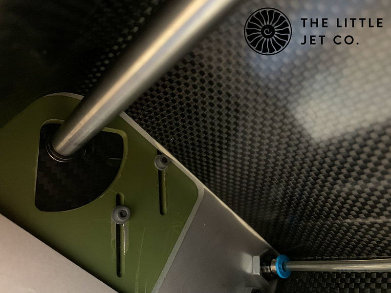
Another week past and the new replacement components arrived. These were then inspected, polished to the specified RA, bushings and O-rings installed, greased and finally installed into the pivot block. This of course is what I should have done the first time...Let us never mention this again!
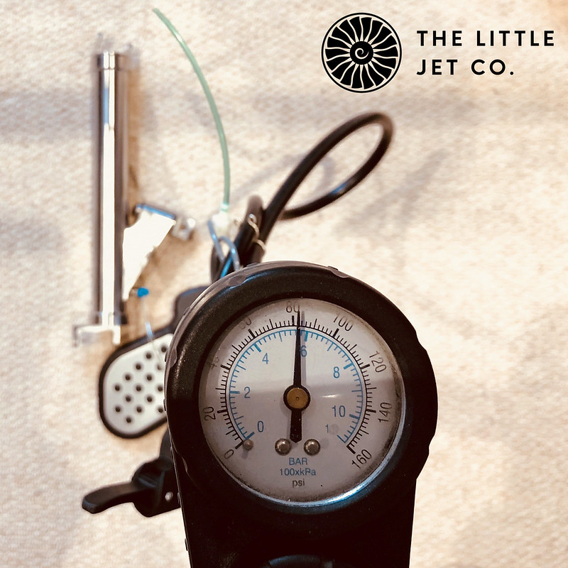
I can now see if the ski would at least push into place. The below video shows my initial thoughts.
https://www.youtube.com/watch?v=Uyhr-2MBVqIYay… although actuating it on what is a very short moment is still making me nervous, less so than before though…

 _DSC4619 by Alex Jones, on Flickr
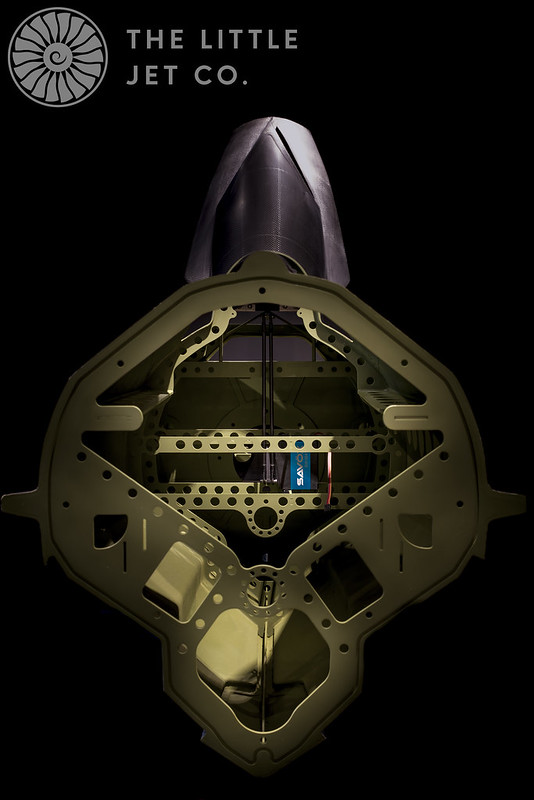 _DSC4620-2 by Alex Jones, on Flickr