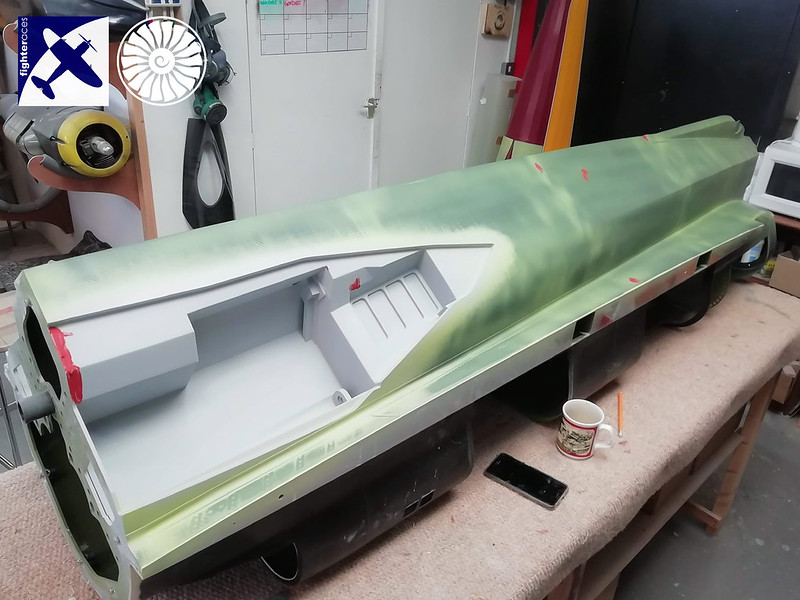
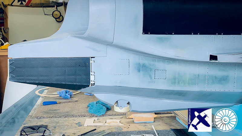
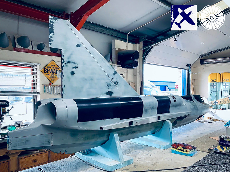
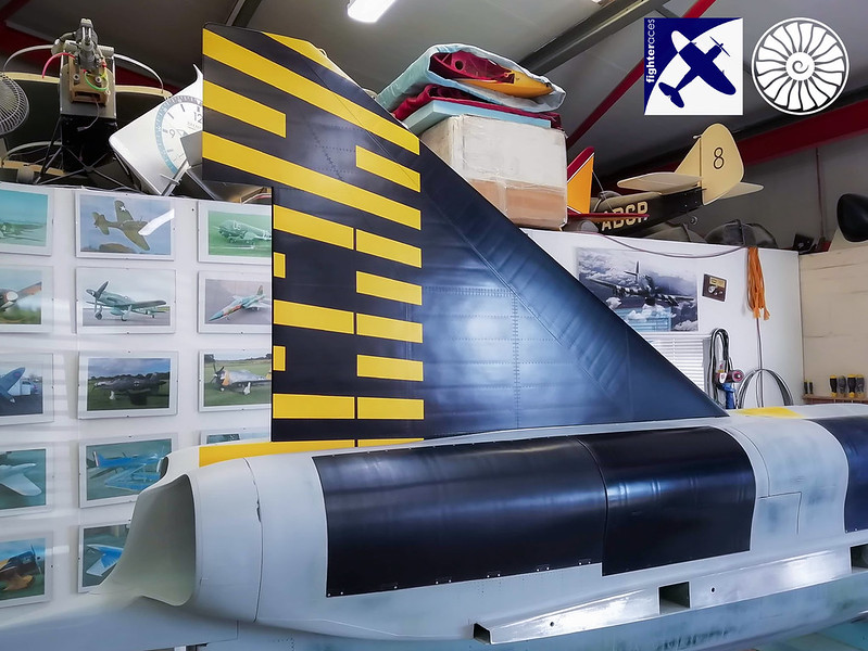
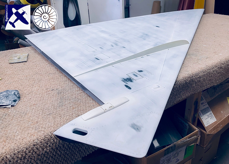
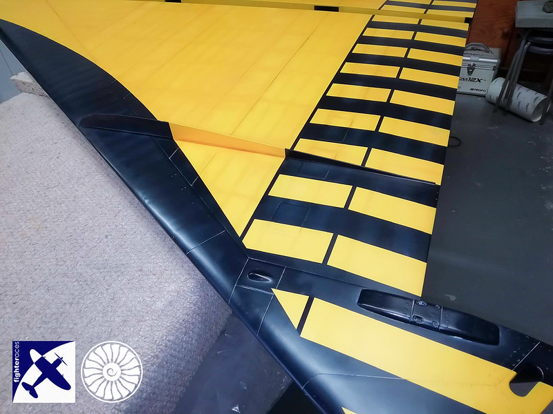
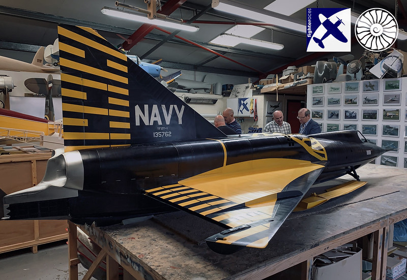
The construction and finished components.
 IMG_0557 by Alex Jones, on Flickr
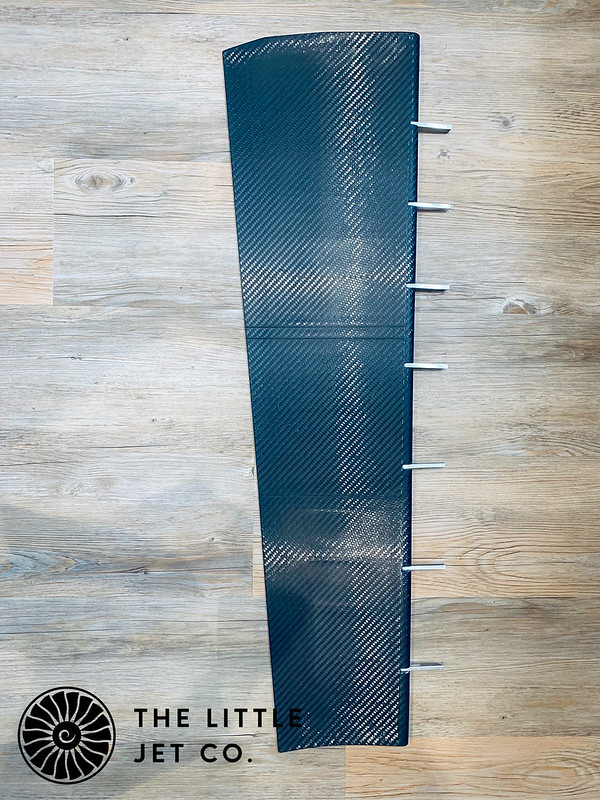 IMG_0626 by Alex Jones, on Flickr
 IMG_0657 by Alex Jones, on Flickr
 IMG_0656 by Alex Jones, on Flickr
The main issue we’ve had is the elevons are impossible to balance in themselves and the actuation is on the pivot so there is no moment arm to help the servos. We didn’t want servos in the wing due to the the bottom of the wing sitting on the water and we didn’t like the idea of having them in the top of the wing. I originally planned on two Ditex servos ganged together actuating the elevon from within the fuselage. It was immediately clear that this was problematic, it works in CAD but just didn’t feel right once installed. It’s one thing to look at the numbers on the screen but there is no substitute for actually doing it and deciding. I used one servo to test the geometry with the telemetry feedback from these servos proving very useful. I had never been entirely happy with the set up so it didn’t come as much of a surprise to see the servo struggle. Just to hold the elevon neutral required 7kgs of torque. There are arguments that the static flight loads on the servo will reduce when neutral etc... when your sentence starts with “it will probably be fine” you know it’s time to go back to the drawing board.
The torque requirements of the surface aren’t outrageous considering its size. A deflection of 40 degrees at 100kts and 12 degrees at 250kts requires around 1000ozin of torque but our new set up will far exceed this. The full size had a maximum elevon deflection of 40 degrees up and 29 degrees down.
Talking with the Phil and John at Fighteraces we came up with a much better way of doing things. The one thing we are not short of with this model is space in the fuselage. This allows us to counterbalance the elevons inside the fuselage. We then decided on using two SP50 servos per elevon mounting them over the CG and using carbon pushrods to the pivot arm. These servos are powered separately and at 8.4 volts produce a combined torque of 183kgcm (2540ozin). By mounting the two servos in an orientation that allows a plate to be fixed between the two servo arms we can cut a slot in one of the fixing points to the servo horn allowing the elevon a degree of freedom even if one of the servos failed in a fixed position. This is nothing new and used in large models without issue it’s just now we can see a way to integrate that principle into the SeaDart. I’ll post some pictures once I’ve finished the design as the above might not make much sense. At least this is a modification which can be installed into the complete airframe without much issue.


